 One of the common misconceptions in using a reticle scale in an optical system is that the reticle scale (or pattern) noted dimensions will be the dimensions of the sample being measured within the optical instrument.
This is a major misconception and is not true.
When a scale length (or pattern) dimensions are referenced on a reticle, it refers only to the physical length (or pattern) on the reticle. Un-calibrated, the reticle’s image (scale or pattern) has no direct bearing on measurements taken with the optical instrument.
To determine the true measurable length (or pattern) dimensions, the reticle must be calibrated to the specific magnifications within the optical instrument.
CALIBRATING A RETICLE IN AN OPTICAL SYSTEM
Preparations: To calibrate a reticle, it must be first placed within the viewing path of the optical instrument. Traditionally the reticle is placed within the eyepiece. In some incidents, for other optical instruments, the reticle is to be mounted in the optical path within the instrument. To determine the exact placement and how to install the reticle, consult your optical instrument’s owners manual. Before installation, clean the reticle thoroughly to remove all oil, dirt, dust and debris from both surfaces. To insure that no damage is done while cleaning, use only recommended optical cleaning liquids, tissues, cloths and other products such as those found at Edmund Optics, VWR, Wards Scientific, Newport or other optical industry suppliers. After cleaning, handle the reticle carefully, by the edges, so not to further contaminate the reticle’s surface.
Calibration:
 1. Once the reticle is in place and visible within the optical system, place the linear or image analysis stage micrometer, such as the APPLIED IMAGE SM, IAM or ACM series stage micrometer scale or calibration pattern on the optical instrument’s stage / platform.
2. Select the objective lens (magnification) to be calibrated.
3. Within the field of view, center and focus the optical instrument on the scale or pattern.
4. Illuminate the scale/pattern image so that the scale lines are fully visible. Do not over illuminate so that the lines appear smaller (or washed out).
5. Determine the longest length visible in a single field of view that covers the entire length of the reticle scale or pattern.
NOTE: Calibrating the entire length of the reticle scale is more accurate than attempting to calibrate a single pair of bars.
6. Divide the overall length noted by the number of bars divisions within the scale or pattern. The resulting number will be the physical distance for that specific objective (magnification) between each bar.
7. Repeat this process for each objective or magnification within the optical instrument system.
CALIBRATION EXAMPLE
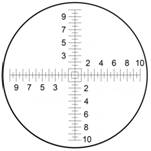
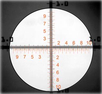 The reticle scale has 20 major and 20 minor divisions for a total of 40 increment divisions in both the X & Y axis.
The calibration scale has 0.01mm increment markings.
There are 171 calibration scale increments from the extreme left to the extreme right of the reticle scale.
Multiplying the 171 increments by 0.01mm it equates to a 1.71mm length. Dividing the 1.71mm length by 40 reticle scale incre-ments, it equals 0.04275mm. Thus, each reticle increment for this magnification is 0.04275mm in length.
The above process is for fixed objectives or magnification. Due to the uniqueness of stereo microscopes or zoom lenses, it is best to calibrate at the minimum and maximum magnifications, as well as any “click stops” within the variable magnifications. If there is not any “click stops” on the zoom, mark on the lens housing at the point where the calibration is taken.
Once the optical system is calibrated, to insure the accuracy of any given measurement, it is recommended that you periodically check the objective / magnification calibration, primarily at the beginning and end of each usage of the optical instrument. This is extremely true for all stereo microscopes and zoom lens measurements systems, since there is a variable in the magnification settings.
ADDITIONAL INFORMATION
For further sharpness of any image viewed when using a compound microscope, make sure the condenser is set up and aligned properly.
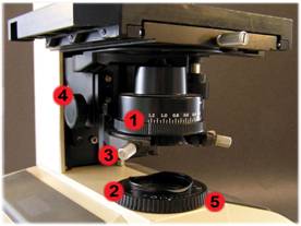
Most microscopes have a focusable condenser. If the condenser has a field diaphragm, numerical aperture scale ring, vertical condenser focusing and centering knobs, it can be aligned for Koehler Illumination (focused illuminated light source).
 The procedure to align a focusable condenser is achieved by:The procedure to align a focusable condenser is achieved by:
1) place a slide on the microscope stage and focus-ing on the slide
2) move the slide to a clear area
3) match the condenser’s Numerical Aperture Scale to the objective’s Numerical Aperture designation
4) reduce the Field Diaphragm to its smallest size
5) center the light within the field of view using the condenser centering knobs
6) using the Condenser Focusing Knobs (not the microscope focusing knob) focus until the field diaphragm edges can be seen sharply
7) expand the Field Diaphragm to just outside the field of view
The microscope is now in proper Koehler Illumination for the given objective. This procedure should be performed each time as each objective is changed.